


|
|
|
|
|
|
|

|
| WELCOME TO EQUINOXE ELECTRONICS |
|
|
|
|
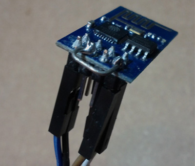
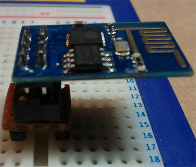
The ESP8266 Module can be utilised in many ways, direct connection to the Arduino or external MCU, or utilizing
the on board MCU. One thing you will notice is that is not 'breadboard fiendly' as such, so you will need to either build a caddy, or use connector cables. |
|
|
|
|
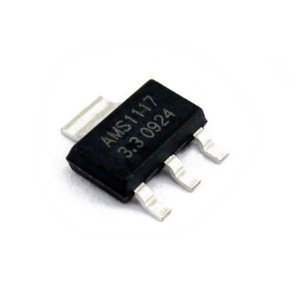
As we feel that these components are fundamentally important to getting this unit up and running, we supply them FREE with every unit purchased through us. Use a suitable power supply, anything from 5-9v should be ok, anything above that may cause problems. | |
|

|
|
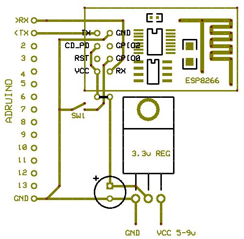
If you notice on your ARDUINO that pin 0 is marked as '>RX' I think this is a little confusing as it seems to mean TO RX, in otherwords TX. In the same way pin 1 is marked as '<TX' is actually FROM TX, in other words RX. so... PIN 0 of your ARDUINO needs to connect to the RX pin of the ESP module. PIN 1 of your ARDUINO needs to connect to the TX pin of the ESP module. | |
|
|
|
Chances are, your ARDUINO may have some code already running on it from your last project, so you need to upload a blank sketch from the Arduino IDE software, there is one already in FILE > EXAMPLES > BASICS > BAREMINIMUM. If you dont, it will most likely interfere with the serial monitor which you are needing to use to talk to the device. It is best to disconnect the ESP module from your arduino while you are uploading, as having the serial connections attached can interfere with the upload. The blank progamme you need to upload will look something like:
void setup(){
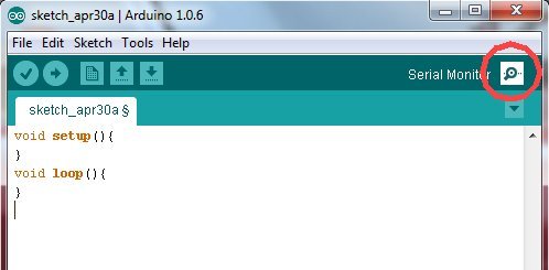
} void loop(){ } Once this is uploaded, re-connect your module and start the 'serial monitor' on your Adruino IDE software (Circled Below). | |
|
|
|
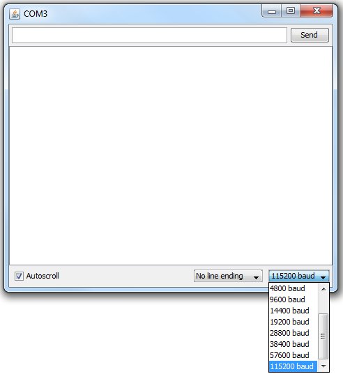
The BAUD rate will need to be set, which may be a bit of trial and error, but all the ones we have received have been
115200 baud rate 'out the box' until flashed with the later firmware which will be 9600. If you change BAUD rates, power-cycle the ESP to re-establish connection. |
|
|
|
|
If all is good, after a bit of pre-amble...you should get an'ok' as in the picture below. |
|
|
ESP8266 Flasher. LUA Uploader NODE MCU |
|
|
FIRMWARE
AI-v0.9.5.0 ESP_8266_BIN092 |
|
|
LINKS ESPLORER ESPLORER NODE MCU NODE MCU - (GIT HUB) ELECTRO DRAGON FIRMWARE |
|

|
|
PINOUTS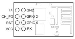
|
|

|

|

|