

|
|
|
|
|
|

|
| WELCOME TO EQUINOXE ELECTRONICS |
| ESP8266 WiFi MODULE | |
|
The ESP8266 Module is a neat little 802.11 b/g/n WiFi module that can either be utilized by interfacing with an external MCU
such as the Arduino or it does have an onboard CPU and a neat self-contained programming language of it's own. With onboard general
purpose I/O ports which can connect to a multitude of sensors makes it an ideal candidate for numerous projects such as a weather station,
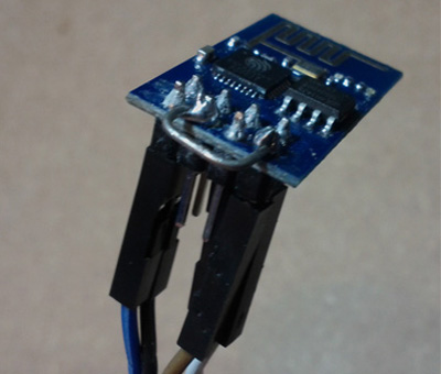
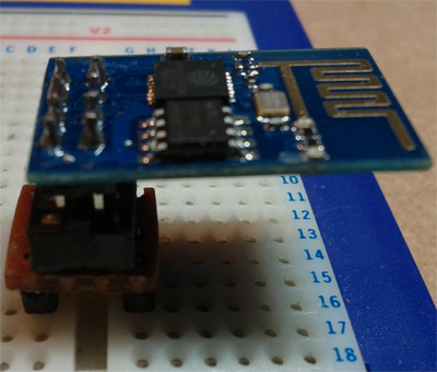
wearable electronics, baby monitor etc. One thing you will notice is that is not 'breadboard fiendly' as such, so you will need to either build a caddy, or use connector cables. |
|
|
|
|
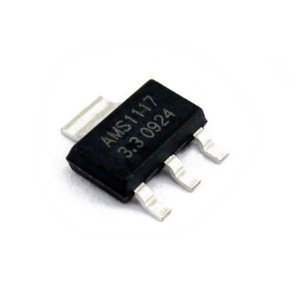
As we feel that these components are fundamentally important to getting this unit up and running, we supply them FREE with every unit purchased through us. Use a suitable power supply, anything from 5-9v should be ok, anything above that may cause problems. | |
|

|
|
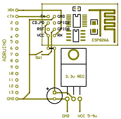
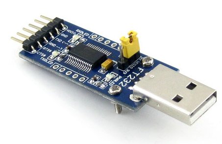
If you notice on your ARDUINO that pin 0 is marked as '>RX' I think this is a little confusing as it actually means TO RX, in otherwords TX. In the same way pin 1 is marked as '<TX' is actually FROM TX, in other words RX. so... PIN 0 of your ARDUINO needs to connect to the RX pin of the ESP module. PIN 1 of your ARDUINO needs to connect to the TX pin of the ESP module. If you are using a USB to RS232 UART, connect the TX of the ESP module to the RX pin of the USB UART and connect the RX of the ESP module to the TX pin of the UASB UART. | |
|
|
|
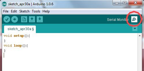
Chances are, your ARDUINO may have some code already running on it from your last project, so you need to upload a blank sketch from the Arduino IDE software, there is one already in FILE > EXAMPLES > BASICS > BAREMINIMUM. If you dont, it will most likely interfere with the serial monitor which you are needing to use to talk to the device. It is best to disconnect the ESP module from your arduino while you are uploading, as having the serial connections attached can interfere with the upload. The blank progamme you need to upload will look something like:
void setup(){
} void loop(){ } Once this is uploaded, re-connect your modules RX & TX lines and start the 'serial monitor' on your Adruino IDE software (Circled Below). You can of course use another terminal program such as 'PUTTY' or 'COOL TERM', but the Arduino serial monitor is just as good for this purpose. | |
|
|
|
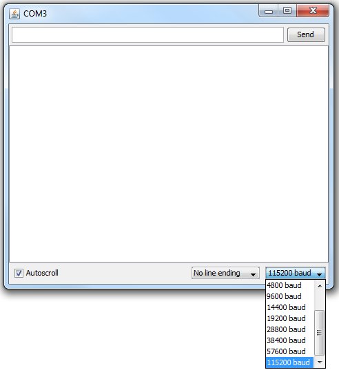
The BAUD rate will need to be set, which may be a bit of trial and error, but all the ones we have received have been
115200 baud rate 'out the box' until flashed with the later firmware which will be 9600. |
|
|
|
|
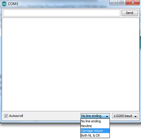
Also ensure that the behaviour is set to 'Carriage Return' or you will see feedback from the ESP module, but you will not be able to
send any data to it.
|
|
|
|
|
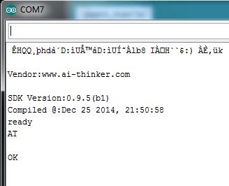
Power-on the module and if all is good, after a bit of pre-amble...you should get an'OK' or 'ready' as in the picture below. If you are getting just garbage on the serial monitor screen - try changing the baud rate, if you are getting no characters displayed, check the power LED on the module is on, check that the data leads are the correct way round and power cycle the module. |
|
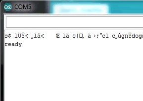
|
|
|
Hopefully you have the 'ready' up on the screen in your serial monitor, all we need to do now is make sure that the module can accept
commands before we attempt up 'flash' the firmware. Type 'AT' (in capitals) in the 'input' area of your serial monitor, and you should receive an 'OK' back.
|
|
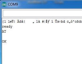
|
|
|
|
|
|
There are a number of Firmware Programmers around for the ESP8266, but the one I use is the
node mcu uploader. The reason for choosing this one is that not only will it flash the firmware for the AT commands allowing you to interface with your Arduino, but will also flash the LUA firmware on to the module, it just seems to make sense to use one flasher for this, but links to all the flashers are in the DOWNLOAD section. You will also need to obtain the latest firmware, we keep a known working copy in the DOWNLOAD section as it's hard to determine a definitive source for this, but I've included links to help you on your way in that section too. Once you have downloaded the node mcu firmware uploader. and unzipped it, run the ESP8266Flasher.exe which can be found in ..\nodemcu-flasher-master\Win32\Release or nodemcu-flasher-master\Win64\Release (depending on your version of OS. Connect the GPIO0 pin of the ESP8266 module to GND and power up the module. (Connecting the GPI00 pin to GND puts the module into 'firmware upgrade' mode.) Select The correct COM port on the NODEMCU FIRMWARE PROGRAMMER form the pulldown list. |
|
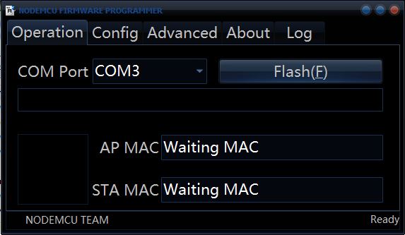
|
|
|
Once you've selected your COM port, click on the 'Config' tab. In the left column, you can remove the little crosses in the check boxes except the top row as we are only uploading one file. Click on the 'COG' and navigate to where your firmware 'AI-v0.9.5.0 AT Firmware.bin' file is located (or whatever version you are uploading) Ensure that in the 'offset' column, it is set to 0x00000, (this is the area of memory we are copying it to.) |
|
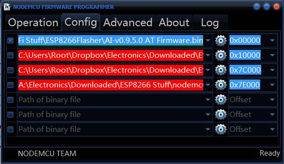
|
|
| Under the ADVANCED tab, there are some settings that you shouldn't need to alter, but click on 'Restore Default' to ensure that everything is as it should be. Note that the baud rate is set pretty high (576000), this seems to be fine, but if you do have issues, you could try lowering this. I know 9600 does work but it will take a while to upload at this speed. | |

|
|
|
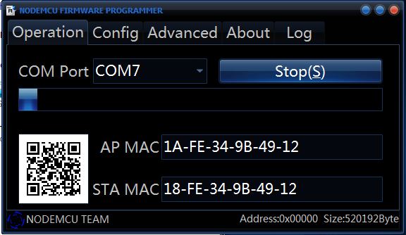
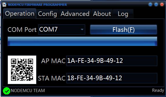
We are now pretty much ready to flash the unit. Click on the 'Operation' tab, and click on the FLash Button. If all is ok, you should see the MAC address of the unit, a QR code, and a progress bar should slowly move across. Once complete, you should see a little green tick in the bottom left corner as shown in the right hand picture below. |
|
|
|
|
|
|
|
If you have you have made it this far, all you need to do now is Power Off the module, Close the NODEMCU software,
Remove GPIO0 from GND and use PUTTY of ARDUINO IDE again to connect via the Serial Monitor as described earlier under the FIRST BOOT
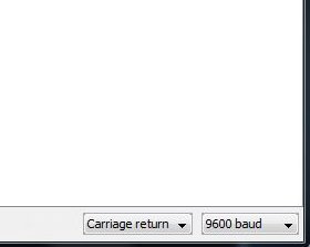
section. Remember to ensure a BLANK SKETCH is loaded onto you ARDUINO to avoid and conflicting Serial Communications. The AI-THINKER firmware runs at 9600 baud, so remember to turn the baud rate down on the serial monitor. Power on the module, and after some pre-amble, you should see the 'ready' screen rather like the right-hand picture below. |
|
|
|
|
|
|
|
At the moment, the AT commands all seem to be case sensitive, so if you type AT, and press return...you should receive
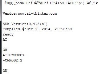
'OK' in the feedback window. If this is the case, all is good and you have 2-way comms. The module supports 3 modes, AP/STA/MIXED. To see what mode the module is in, type AT+CWMODE? and press return. You will be returned '+CWMODE:' and then 1, 2 or 3. +CWMODE:1 = STA Mode - The module acts as a wireless client. +CWMODE:2 = AP Mode - The module acts as an AP with DHCP server. +CWMODE:3 = MIXED - The module is both and acts as a client and an AP As we can see from the output below that my module is in AP mode. |
|
|
|
|
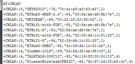
In order to place the module into STA mode, we simply issue the command AT+CWMODE=1 and press enter. You should see 'OK' in the feedback window. We should now be able to list APs visble to the module. Enter the command AT+CWLAP and press enter. This command can take a few seconds to process, but after a couple of seconds you should see output as shown below. |
|
|
|
|
If you get some 'garbage' in the output, this is usually due to the power supply being a little dodgy which is why we suggest using the regulator as mentioned earlier. Using the 3.3v supply from the Arduino tends to cause some garbled output, especially when using the AT+CWLAP command....probably due to the peak in power required. The output is comma delimited and the data shown is in the following format. (Encryption Type, SSID, RSSI, MAC address of AP, Channel) The Encryption field is a numeric value 0 - 4 in the following format: 0 = OPEN 1 = WEP 2 = WPA-PSK 3 = WPA2-PSK 4 = WPA-WPA2-PSK In order to connect to one of the listed APs, we need to use the AT+CWJAP="SSID","Password" command. You will need to replace the SSID and Password with your router details, eg: AT+CWJAP="BTHub5-6MSF","Q5H3d34F" You should, as usual, get an 'OK' sent back if all is good. OK, last things last, lets check out basic connectivity. If we now issue the command AT+CIFSR ,we should see results alone the lines of: AT+CIFSR 192.168.0.10 This is along the lines of 'IPCONFIG' on your PC. So, on your PC (assuming that this is also connected to the same AP of course), open a command prompt and type 'PING 192.168.0.10' (replacing the 192.168.0.10 with the IP address you got in the result of the AT+CIFSR command). You should see the ping replies from your module. |
|
|
******** SORRY GUYS......I'M STILL WORKING ON THIS SITE!! ********* |
|

|

|
PINOUTS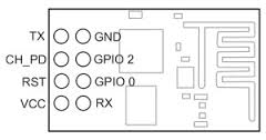
|
|

|

|

|